- Artikel-Nr.: 211066
- Hersteller: ALLNET
- Hersteller Artikel-Nr.: ALL-SG8428v2PM
- EAN Nummer: 4038816211064
- Gelistet seit: 14.06.2022
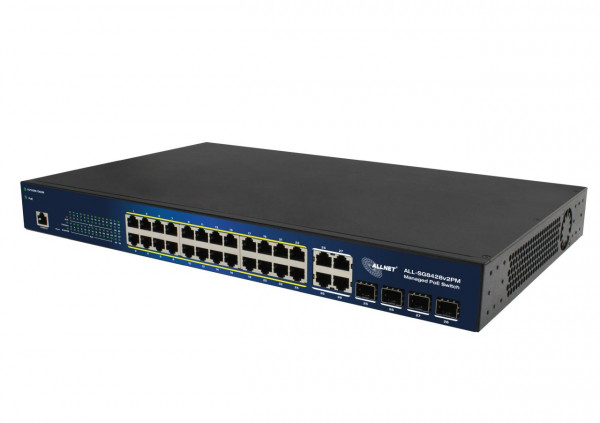
ALLNET Switch smart managed Layer2 24 Port • PoE Budget 370W • 24x PoE at • 4x SFP • 19" • ALL-SG8428v2PM
Highlights:
- 24 Port Gigabit non-blocking Switch Architektur
- Unterstützt NWay Protocol (10/100/1000Mbps) und Duplexmodus (half/full) Auto Detektion
- support back-pressure (half duplex), flow control (IEEE 802.3x und IEEE 802.3az Energy Efficient Ethernet
- VLAN: Port basiert / Tagged basiert
- Link Aggregation (IEEE802.3ad LACP)
- IGMP Snooping (v1/v2)
- QoS (Port Based, Flow, 802.1p, IP-TOS, IP DSCP)
- Stormcontrol (Broadcast, Multicast, Unicast)
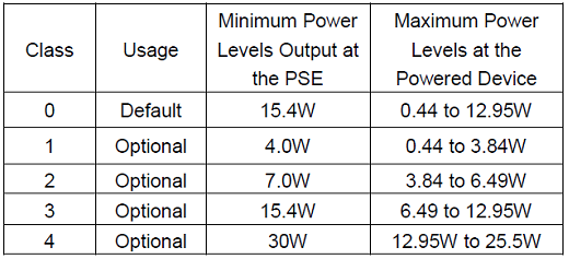
- 370W PoE Budget unterstützt PoE IEEE802.3af/at PSE-Devices
Der neue ALLNET ALL-SG8428v2PM Switch stellt eine optimale Basis für kleine und mittlere Arbeitsgruppen mit hohem Netzwerk- und Datenaufkommen dar und ermöglicht eine schnelle Datenübertragung im Netzwerk. Mit insgesamt 24 abwärtskompatiblen Gigabit Ports sind die angebundenen Rechner und Server zuverlässig und leistungsstark miteinander verbunden. Der ALL-SG8428v2PM kann durch das interne 450W Netzteil ein maximales PoE Budget von 370W an die Endgeräte weiterreichen. Die 24 Gigabit PoE Ports unterstützen den PoE Standard IEEE802.3af und den IEEE802.3at Standard. Im Switch sind seitlich 2 Lüfter verbaut.
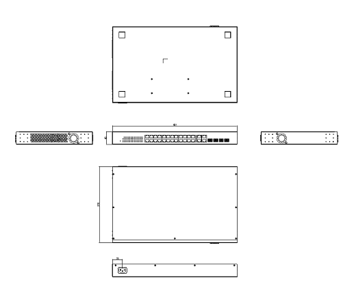
Mechanical Drawings:

Technische Details:
| Items | Specifications |
| Model No. | ALL-SG8428v2PM |
| Key Components | RTL8382M+RTL8218Dx2+RTL8214FC Flash IC:16MB DDR: 1Gb IP808ARx3 PSE controller |
| I/O ports | 24x GbE ports, RJ45 4 x port GbE SFP/RJ45 combo Reset Button: reset to default setting, re-start system |
| PoE ports | Port# 1~ 24 IEEE802.3at, IEEE802.3af |
| LED Define | PWR/SYS: Green LED
PoE Alert: Green LED
ALM: Red LED
Port LED: RJ45:
PoE:
SFP: - Off: disconnected or fail - Green: 100/1000Mbps connected - Blinking: data transmitting |
| HW feature | IEEE802.3 10BASE-T IEEE802.3u 100BASE-TX IEEE802.3ab 1000BASE-T IEEE802.3az EEE IEEE802.3x IEEE802.3z IEEE802.3at, IEEE802.3af MAC address Table: 8K Packet buffer size: 4.1M Jumbo Frame: 10K bytes 56Gbps switching capacity Forwarding rate: 41.66Mpps (64-byte package size) |
| Data Transfer Rate | Ethernet:10 Mbps (half duplex),20 Mbps (full duplex) Fast Ethernet:100 Mbps (half duplex),200 Mbps (full duplex) Giga Ethernet:2000 Mbps (full duplex) |
| PoE power pin-out | Alternative A (Pin 1,2/3,6) |
| PoE Output power capacity | Maximum output :30W per each port
|
| System Monitor | HW Monitor IC: ADT7476
|
| Power Input | Internal power supply Input: 100-240V AC Output: 450W |
| PoE Power Budget | 370W |
| Reset button | Support reset to default configuration |
| Dimension | 441(W) x 270(D) x 45(H) mm |
| FAN Design | 6300 Fanx2 (Smart Fan) |
| Temperature | Operating: -5~ 50? Storage : -40 ~ 70? |
| Humidity | Operating: 10% ~ 90% RH (non-condensing) Storage: 5% ~ 90% RH (non-condensing) |
-
- Software Feature
| Status | System Information | ||
| Logging Message | |||
| Port | Statistics | ||
| Error Disabled | |||
| Bandwidth Utilization | |||
| Link Aggregation | |||
| MAC Address Table | 8K | ||
| Network | IP Address | Static / Dynamic | |
| System Time | SNTP / From Computer / Manual Time | ||
| Port | Port Setting | State / Speed / Duplex / Flow Control | |
| Error Disabled | Recovery Interval | ACL / ARP Rate Limit / BPDU Guard / Broadcast Flood / DHCP Rate Limit / Port Security / Self Loop / Unicast Flood / Unknown Multicast Flood | |
| Link Aggregation | Group | ||
| Port Setting | State / Speed / Flow Control | ||
| LACP | |||
| EEE | |||
| Jumbo Frame | 9K Byte | ||
| PoE | Global Setting | Schedule Status | |
| Priority Setting | |||
| Power Limit | |||
| Power Show | |||
| VLAN | VLAN | Create VLAN | |
| VLAN Configuration | |||
| Membership | |||
| Port Setting | |||
| Voice VLAN | Property | ||
| Voice OUI | |||
| Protocol VLAN | Protocol Group | ||
| Group Binding | |||
| MAC VLAN | MAC Group | ||
| Group Binding | |||
| Surveillance VLAN | Property | ||
| Surveillance OUI | |||
| GVRP | Property | ||
| Membership | |||
| Statistics | |||
| MAC Address Table | Dynamic Address | Aging Time | |
| Static Address | |||
| Filtering Address | |||
| Spanning Tree | Property | State / Operation Mode / Path Cost / BPDU Handling | Operation Mode : STP/RSTP/MSTP |
| Port Setting | |||
| MST Instance | |||
| MST Port Setting | |||
| Statistics | |||
| Discovery | LLDP | Property | |
| Port Setting | |||
| MED Network Policy | |||
| MED Port Setting | |||
| Packet View | |||
| Local Information | |||
| Neighbor | |||
| Statistics | |||
| Multicast | General | Property | Unknown Multicast Action / Multicast Forward Method |
| Group Address | |||
| Router Port | |||
| Forward All Table | |||
| Throttling | |||
| Filtering Profile | |||
| Filtering Binding | |||
| IGMP Snooping | Property | State / Version / Report Suppression | |
| Querier | |||
| Statistics | |||
| MLD Snooping | Property | State / Version / Report Suppression | |
| Statistics | |||
| MVR | Property | State / VLAN / Mode / Group Start / Group Count / Query Time | |
| Port Setting | |||
| Group Address | |||
| Security | RADIUS | ||
| TACACS+ | |||
| AAA | Method List | ||
| Login Authentication | Console / Telnet / SSH / HTTP / HTTPS | ||
| Management Access | Management VLAN | ||
| Management Service | Telnet / SSH / HTTP / HTTPS / SNMP / Session Timeout | ||
| Management ACL | |||
| Management ACE | |||
| Authentication Manager | Property | ||
| Port Setting | |||
| MAC-Based Local Account | |||
| WEB-Based Local Account | |||
| Sessions | |||
| Port Security | |||
| Protected Port | |||
| Storm Control | State / Broadcast / Unknown Multicast / Unknown Unicast / Action (Drop / Shutdown) | ||
| DoS | Property |
| |
| Port Setting |
| ||
| Dynamic ARP Inspection | Property | ||
| Statistics | |||
| DHCP Snooping | Property | ||
| Statistics | |||
| Option82 Property | |||
| Option82 Circuit ID | |||
| IP Source Guard | Port Setting | ||
| IMPV Binding | |||
| Save Database | |||
| ACL | MAC ACL | ||
| MAC ACE | |||
| IPv4 ACL | |||
| IPv4 ACE | |||
| IPv6 ACL | |||
| IPv6 ACE | |||
| ACL Binding | |||
| QoS | General | Property | CoS / DSCP / CoS-DSCP / IP Precedence |
| Queue Scheduling | Strict Priority / WRR | ||
| CoS Mapping |
| ||
| DSCP Mapping |
| ||
| IP Precedence Mapping |
| ||
| Rate Limit | Ingress / Egress Port |
| |
| Egress Queue |
| ||
| Diagnostics | Logging | Property | Console / RAM / Flash |
| Remote Server |
| ||
| Mirroring |
|
| |
| Ping |
|
| |
| Traceroute | |||
| Copper Test | |||
| Fiber Module | |||
| UDLD | Property | Message Time | |
| Neighbor | |||
| Management | User Account |
|
|
| Firmware | Upgrade / Backup | Action (Upgrade / Backup) / Method (TFTP / HTTP) | |
| Active Image | Active Image / Backup Image | ||
| Configuration | Upgrade / Backup | Action (Upgrade / Backup) / Method (TFTP / HTTP) | |
| Save Configuration | Source File / Destination File, Restore Factory Default | ||
| SNMP | View |
| |
| Group | |||
| Community | |||
| User | |||
| Engine ID | |||
| Trap Event | Authentication Failure / Link UP_Down / Cold Start / Warm Start | ||
| Notification |
| ||
| RMON | Statistics | ||
| History | |||
| Event | |||
| Alarm | |||
| Marks | Safety | LVD EN62368-1:2014 | |
| EMC | CE EN55032: 2015+AC:2016 | class A | |
| FCC Part15, Subpart B: ANSI C |
| Belüftung Switch: | Mit Lüfter |
| LAN Geschwindigkeit: | 1Gbit/s |
| Management: | smart managed (WebGui) |
| Einsatzort Switch: | 19" |
| PoE Budget: | <500 Watt |
| PoE Port Leistung: | 30W at |
| SFP Geschwindigkeit: | SFP 1GBit |
| SFP Port Anzahl: | 4 |
| Anzahl Ports PoE/LAN: | 24/0 |


